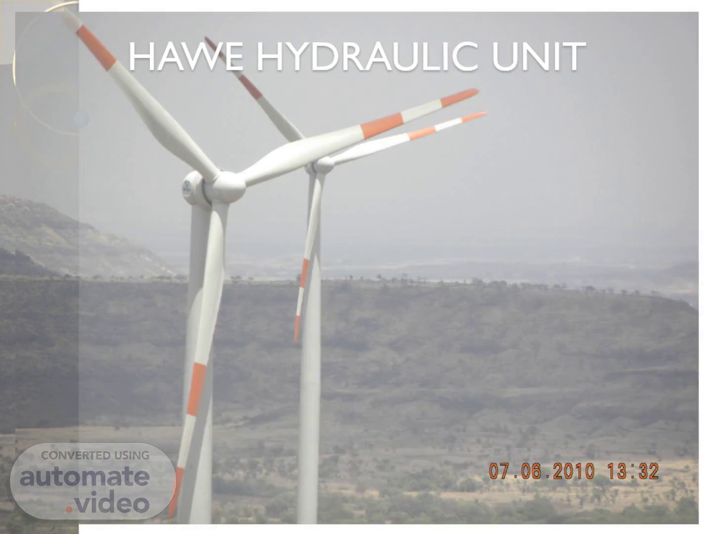
Scene 1 (0s)
HAWE HYDRAULIC UNIT.
Scene 2 (5s)
Accumulator: A compressed gas accumulator consists of a cylinder with two chambers that are separated by an elastic diaphragm. One chamber contains hydraulic fluid and is connected to the hydraulic line. The other chamber contains an inert gas under pressure (typically nitrogen) that provides the compressive force on the hydraulic fluid..
Scene 3 (21s)
dcv.pdf (SECURED) - Adobe Reader. Filter: A filter is a device that removes particles from a given liquid or gas. It can disposable medium for removing fine particles of specified micron sizes. Strainer: A strainer are used to screen or remove larger particles from a line. Directional Control valve: Directional control valves are components which change the direction of hydraulic fluid in hydraulic system by opening or closing of valve. They are used to control the direction motion of power..
Scene 4 (43s)
[image] MAGNETIC FORCES LAND AREAS Low pressure I retum flow -PLUNGER High pressure.
Scene 5 (1m 6s)
纯液压技术 英文版讲义.pdf (SECURED) - Adobe Reader. [image].
Scene 6 (1m 31s)
V-77 HAWE HYDRAULIC UNIT. [image].
Scene 7 (1m 38s)
NORMAL WORKING TIME. [image] (B) '40-SS torn—is V DC.
Scene 8 (1m 45s)
[image] "a-as Pos. N«deiyt.g = Q 1.1 24 KA n/77—1.s.
Scene 9 (1m 54s)
FLUSHING TIME. [image] "ghrge : 2,81 bar Vetschrauburg Nx.rleistung P = = IJ/m 400 V. Hz Q 1.1 a/mir Steuw*mnung 24 DC EO-2„.lc (stdhl) vcesnlr or encn ago er POS Vensys 6 cm pro Doppeltcb.
Scene 10 (2m 7s)
BRAKING PROCESS. [image] 6 cm pro Jdppelü "ghrge : A1. L = Vetschrduburg = IJ/m 400 V. Hz F&deßtrw Q 1.1 '/mir p = btr Steuw*mnung 24 DC EC-2„.lc (stdhl) vcesnlr or encn ale Eerrigbstuck ablasse'. Vensys.
Scene 11 (2m 19s)
[image] 60 B. A1. L L (stil) 24 0.37 Q 1.1 J/min 24 DC 24 vtesn4T.
Scene 12 (2m 28s)
[image] "ghrge : 2,81 bar Vetschrauburg Nx.rleistung P = = IJ/m 400 V. Hz Q 1.1 a/mir p = btr Steux*mnung 24 DC EO-2„.lc (stdhl) vcesnlr or encn ale o er POS Vensys 6 cm pro Doppeltcb.
Scene 13 (2m 40s)
QUESTIONS…?.
Scene 14 (2m 46s)
V82/87 HAWE HYDRAULIC SYSTEM.
Scene 15 (2m 52s)
[image] dr•ulikaqqregaf. NORMAL WORKING TIME.
Scene 16 (2m 59s)
[image] 3-3 - -. YAWING PROCESS.
Scene 17 (3m 5s)
[image] poverp.xk 20. FLUSHING PROCESS.
Scene 18 (3m 12s)
[image] Ot pose rpock &ödik. BRAKING TIME.
Scene 19 (3m 19s)
[image] ussescH must 'Ineo. ROTOR LOCKING PROCESS.
Scene 20 (3m 25s)
[image] gs•a of powerpack CD 10m, 20 dreulikägregat I.S MW.
Scene 21 (3m 34s)
[image] dradik. BRAKE RELEASING PROCESS.
Scene 22 (3m 40s)
QUESTION…?.
Scene 23 (3m 46s)
Do’s. Check pressure fluid level in the tank. Check cleanliness/condition of the pressure fluid. Check filter clogging indicators/difference pressure switches (when apparent) while system is in operation. Check persistent fluid temperature while system is in operation (usually <60°C, max. 80°C). Check operation pressure levels and operation speeds. Check for external leaks. Check piping and tubes for proper mounting and indications of rubbing Check visually the hydraulic accumulators. Check visually all electrical connections of motor, solenoids, sensors, pressure switches, etc. Safety is six letter word and its mean is four letter Life..
Scene 24 (4m 13s)
THANKS.